When you turn on a system with DC-link capacitors, they initially behave like a short circuit. Without a limit, the current would spike far too high.
A precharge resistor solves this problem, provided it is correctly calculated and sized.
In this article, we’ll look at the following:
The moment you turn on a system with DC-link capacitors, they are discharged. Physically speaking, they act like a short circuit for that split second.
Without a limiting resistor, the inrush current would spike to extremely high levels.
The practical consequences:
By correctly calculating and sizing the precharge resistor, we ensure that the capacitor is charged in a controlled manner before the main contactors close.
To perform accurate precharge resistor calculation, we use three key values:
We use the time constant τ for this purpose. In electrical engineering, a capacitor is considered charged after a time of 5 * τ.
If you perform a precharge resistor calculation based on this, you will ensure that the circuit is fully charged before the main contactors are energized.
The highest current flows exactly at the moment of energization (t = 0). This value must not exceed the load limits of your contactors and fuses.
The formula: I_max = U / R
You must also determine this value when performing the precharge resistor calculation, as it is often the deciding factor in component selection.
The resistor must be able to convert all the energy from the charging process into heat without being damaged.
If the system preloads regularly (e.g., 3 times in 10 seconds), a rough estimate is:
P_avg =(E_sum)/(t_sum)=3*E /10 s
This average temperature rise determines whether heat “builds up” (keywords: cycling/heat buildup) and causes the component to overheat.
Be sure to check the following in the datasheet:
To illustrate the precharge resistor calculation in practice, let’s consider the following scenario:
Step 1: Determine the resistance value
First, we check the minimum allowable resistance based on the current limit:
We then calculate the value based on the time limit:
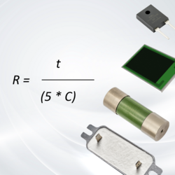
In this case, a resistance of 120 Ω to 200 Ω is ideal. Depending on your priorities (faster charging vs. lower inrush current), you could choose a lower or higher value here. Important: Don’t forget to account for component tolerances!
Step 2: Calculate the energy per precharge cycle
This value is critical for component selection during the precharge resistor calculation:
Simply performing the precharge resistor calculation is just theory. In practice, physical details often determine whether a resistor will last.
Here are the two most common challenges and how to solve them using technology:
During precharging, an enormous amount of energy (E) must be absorbed in a matter of milliseconds. A conventional resistor can be damaged by this localized heat inside the device even before the heat reaches the housing.
✓ The solution: Ensure high pulse resistance. Technologies such as wire-wound resistors can absorb very high amounts of energy in a very short time without sustaining damage. This prevents hotspots and enables reliable operation in a compact design.
If the system is turned on and off frequently, the resistor cannot cool down completely between cycles. Heat builds up.
✓ The solution: Choose a resistor with a high average power rating (P) and ensure adequate cooling.
Miba offers a wide range of high-power resistors using thick-film technology.
These have been specifically designed for high continuous loads and compact designs.
Do you have questions about the precharge resistor calculation, or are you looking for the right resistor for your project?